The story of the people who created the Czechoslovak DAKO air brake The first steps The birth of DAKO Team Tests and refinement International recognition Legacy.
Principle of operation The DAKO function valve has the following pipe connections:
The story of the people who created the Czechoslovak DAKO air brake
This article begins with the story of a team of Czechoslovak engineers who in the 1950s and 1960s developed a revolutionary air brake for railroad cars. The DAKO brake became a standard of quality and contributed to the establishment of Czechoslovakia as a leader in the railway industry.
The first steps
After World War II, Czechoslovakia needed to modernize its railway infrastructure. The existing brake system, based on George Westinghouse’s patent, no longer meets the increasing requirements for safety and efficiency.
The birth of DAKO
In 1953, a team of engineers led by Josef Danek began work on developing a new air brake. After years of hard work and testing, in 1955 the first DAKO brake was introduced.
A team
In Danek’s team, other names stand out, such as Bohumil Forsht, Frantisek Karfik, Milos Reis, Jaroslav Shpatenka, Karel Holub and Antonin Krij. Each of them contributes valuable knowledge and skills to the success of the project.
Tests and refinement
In the 1960s, a new test circuit was built to allow more in-depth research into braking systems. In this period, new DAKO models were also developed, such as the electro-pneumatic brake and the brake for narrow wheels.
International recognition
DAKO has gained international recognition for its quality and reliability. In 2002, Czech brake manufacturers successfully re-homologated DAKO, confirming its status as a benchmark in the industry.
Legacy
Today, DAKO is still used in many railway wagons in the Czech Republic and around the world. The legacy of Danek’s team lives on in the work of subsequent generations of engineers who continue to develop and refine rail braking systems.
Principle of action
Three pressures act on the system from the pistons in the valve (distributor):
- pressure from the main pipeline – IV
- pressure from the distribution chamber – part 3
- pressure from the brake cylinder – location III
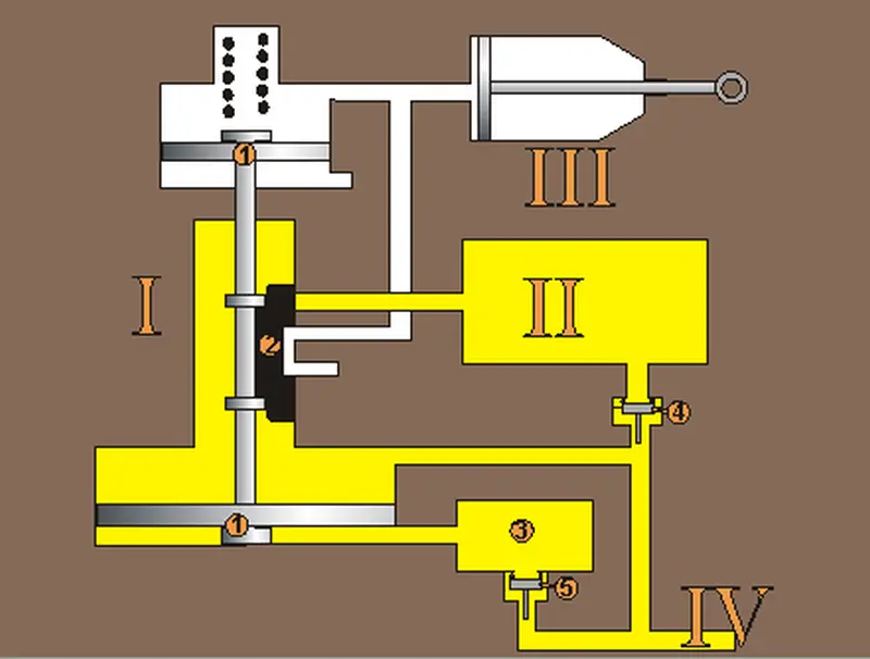
Locations: I – distributor, II – additional air tank, III – brake cylinder, IV – main pipelineParts: 1 – piston system, 2 – gate valve, 3 – distribution chamber, 4 – check valve, 5 – distribution chamber without -check valve
The DAKO function valve has the following pipe connections:
- to main pipe 1
- to auxiliary air tank 3
- to the distribution air tank;
- to the control air tank;
- to the supply pipe;
- to automatic brake release OS1 5